To appropriately understand the design of our car, we first have to clarify what forces apply on the car.
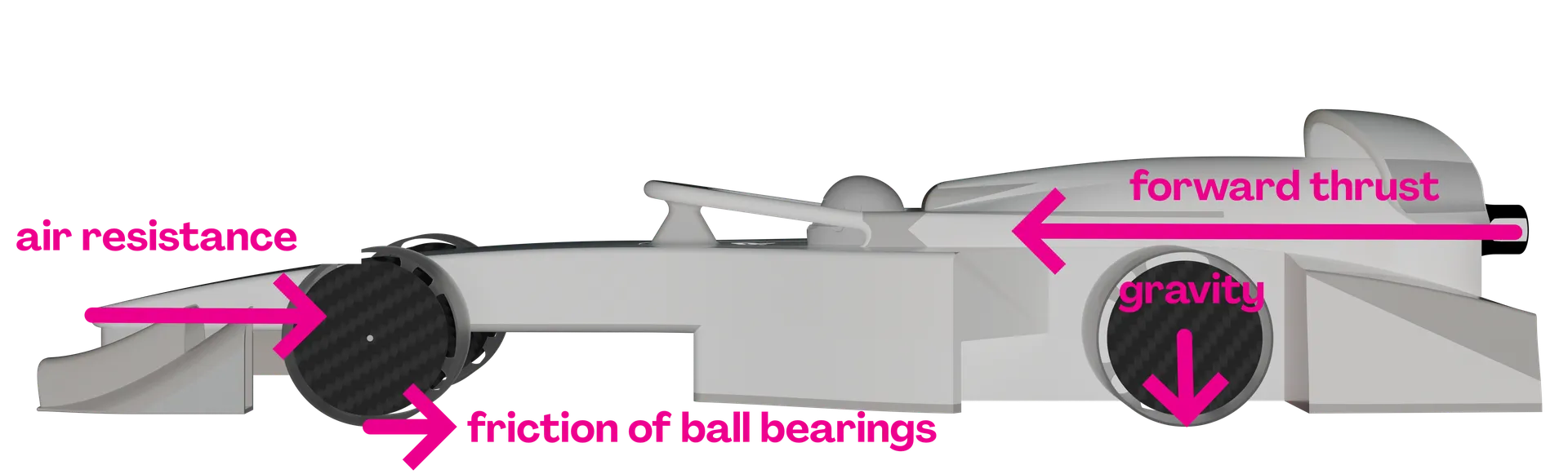
Stored in the cartridge are 8 grams of CO2 gas. As space in the chamber is limited, the gas inside is compressed and the pressure is high. When the cartridge is penetrated, gas releases at the back of the container. With Newton’s third law of motion (actio = reactio) it can be explained that the motion of the gas in one direction leads to a motion of the car into the other direction.
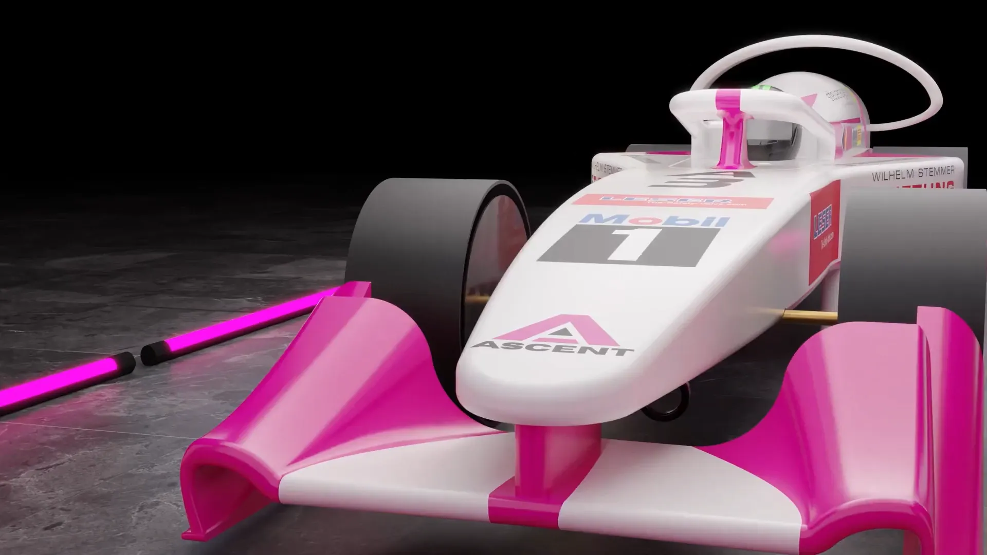
Enzo Ferrari once said, “Aerodynamics are for people who can’t build engines.” Due to the technical regulations implemented by STEM Racing we’re not allowed to modify the accelerating force. Therefore, the quote from Enzo Ferrari doesn’t apply for STEM Racing and we focus on minimizing drag and optimizing components to ensure a fast track time without modifying the accelerating force. To minimize the drag coefficient, which is a value that puts into number, how streamlined an object is, we use various CFD analysis techniques. CFD stands for Computational Fluid Dynamics and one of the techniques we use is the combined flow visualisation. It combines the conventional streamline visualisation with the vector contour plot. The advantage of this technique is that it brings together both concepts to get a better understanding of the air’s direction of movement and at what speed the air moves. With this knowledge we can optimise the shape of the car’s components to make them more streamlined (= lower the drag coefficient). Another technique we use is the drag analysis. With this type of CFD analysis you can calculate the drag coefficient. Additionally, there are various other important CFD analysis techniques that we will not discuss here.
Another force stopping the car is the friction between the rotating wheels and the fixed part of the axle construction. To minimise the friction between these components, we use ball bearings. Testing different ball bearings and axle constructions is a crucial part of real-life testing, because it is hardly possible to simulate the axial forces acting on the ball bearings and the wear of different ball bearing models and manufacturers.
To get a better understanding of our design process, we sectioned it into three aspects:
Aerodynamic research and development (CFD analysis)
In this section we will show you our design process on the example of our side pods.
To understand the design of our car’s side pods, we first need to clarify their function.
The primary goal of the side pod is to guide the airflow behind the open volume of the front wheels away from the rear wheels. Additionally, the side pods should prevent the unavoidable turbulent air created in the wake of the front wheels from interfering with laminar flow areas further downstream.
In the following sections different side pod designs are shown:
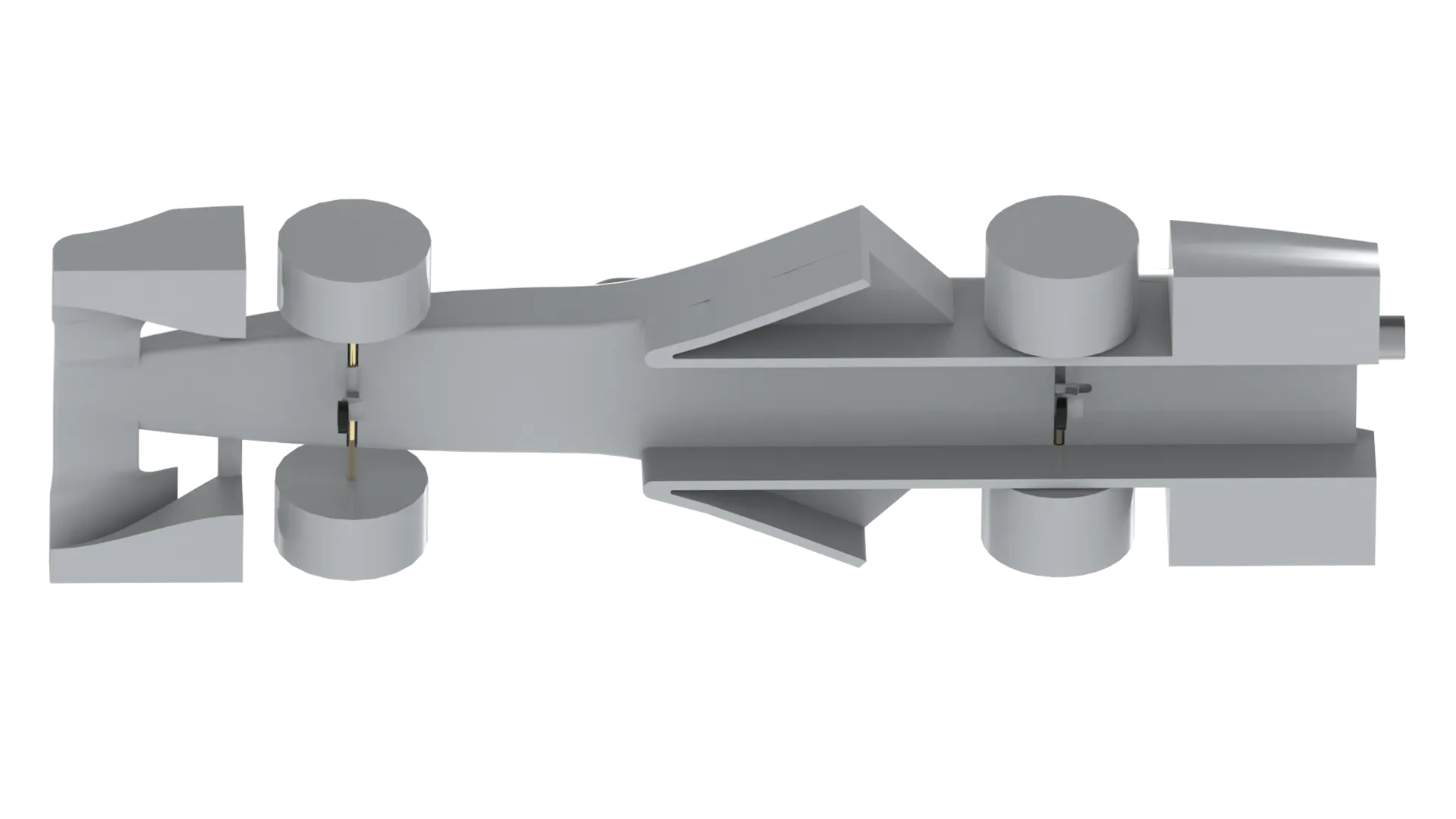
Our first idea was to extend the ramp to its maximum width while retaining the concave profile.
.42.webp)
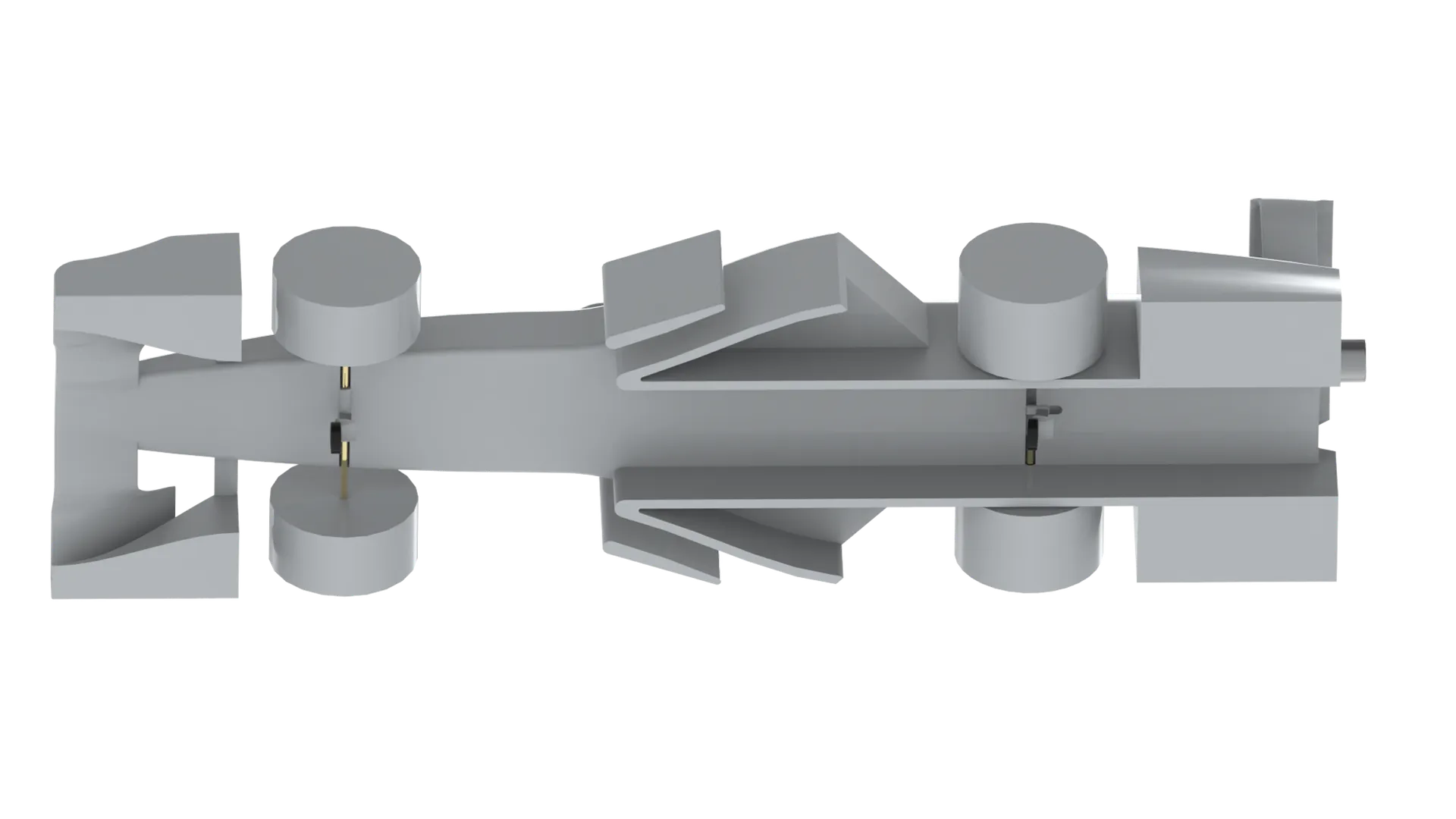
In the following version, the ramp was reshaped from concave into a largely convex form, which resulted in a reduction in drag.
Building on this, a third configuration added a side foil to guide the airflow more effectively around the rear wheel but this led to a slightly higher drag due to interferences between the side foil and the side pod.
As there is a fixed amount of force emitted from the CO2 cartridge, it is important to make the car as lightweight as possible while still maintaining the minimum weight of 55 grams. Newton’s second law of motion (F = ma) describes that the less an object weighs, the higher is its acceleration when applying a certain force. To reach the minimum weight of the cars, we make them hollow on the inside to save weight. As the freedom of design is very good, we use SLS printing to produce our chassis. It is easier than milling it with polyurethane (special hard foam block) because there are less parameters to consider.
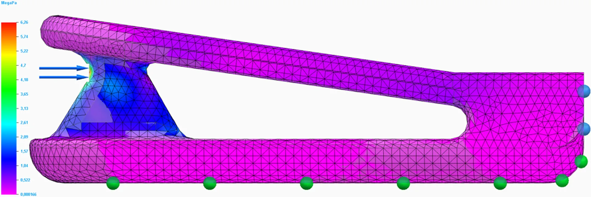
To continually make sure that the wheels, the halo and other components are stable enough to withstand the pressure of impact, we virtually test them with the FEA. The Finite Element Analysis is a simulation that predicts how structures react to forces like stress, heat and vibration. Complex models are divided into smaller elements, forces applying on the car are defined and equations, considering the structural integrity of materials, are solved. After solving the simulation, it is shown if the material is strong enough to withstand a certain force.